
A cutting tool game changer
Peter Probert, European Application Engineer – Tools and Alfredo Barragan, Corporate Application Engineer, Saint-Gobain Abrasives
In today’s challenging economic environment, it’s become more important than ever to increase cycle times and reduce downtime, whatever the application. Machine technology has advanced rapidly, helping manufacturers to increase throughput. However it's essential that abrasive technology evolves to keep up, delivering cutting tools that meet the needs of a number of industries in line with the latest technology.
In this article, we look at the abrasive technology developments that have occurred to help to meet these increasing demands from the results of a set of tests undertaken by the Saint-Gobain Abrasives engineering team, as well as the benefits of pinch grinding and the invisible work of the finishing wheel in the production of cutting tools.
What is pinch grinding? Pinch grinding is a variation of peel grinding, which refers to high-speed cylindrical grinding of rotating blanks. In pinch grinding, however, the blank simultaneously passes through two opposing wheels: a roughing wheel and a finishing wheel. It has traditionally been used only for niche tasks but due to the aforementioned environment, it’s becoming more and more prominent in a number of industries thanks to its reduced cycle time and ability to combine operations. It’s a technique worth considering thanks to the high precision it offers and its capacity to produce small, complex end-products without the need for a profile wheel. The grinding wheel acts like a single-point tool under CNC control so you can easily change profiles without changing wheels. What’s more, it’s perfect for hard materials that conventional machining can’t handle and thanks to the falling cost of CBN, it is becoming a more cost-effective solution. The automotive industry has been particularly interested in pinch grinding due to the need for extreme precision for increasingly complex parts. | 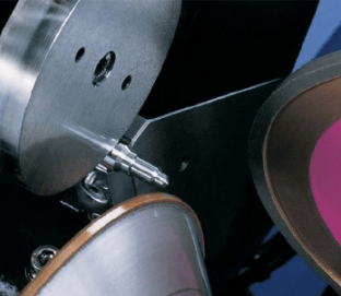
In pinch grinding, the blank simultaneously passes through two opposing wheels: a roughing wheel and a finishing wheel. |
Abrasive technology
Rollomatic has patented pinch grinding using its ShapeSmart grinders to reduce the number of operations required in blank preparation and reduce lead times in response to market demands. To keep up with these machine improvements, abrasive technology has had to evolve fast. Through technical studies, Saint-Gobain Abrasives has developed improved solutions to ensure optimal feed rates at the highest parts per redress in the market for cutting tool blank preparation. Norton application engineers looked at numerous factors when using an engineered approach to develop optimal wheels for pinch grinding to achieve these results.
There are two primary objectives during the preparation of raw solid carbide blanks for the cutting tool market: firstly we need to achieve precise geometrical dimensions on the blank and secondly we want to deliver tight surface finish requirements. Blank preparation usually consists of roughing and finishing blanks individually placed on centreless grinders and OD plunge or traverse cylindrical grinders. These multiple-step operations for cutting tool manufacturers can be time-consuming and costly. In some instances, manufacturers are required to send the blanks to a third party to complete, costing further time and money.
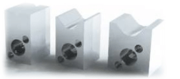
V-block steady rests for pinch grinding | Pinch grinding: two steps in one However, using the pinch grinding technique, it is possible to eliminate the two-step process. With a set-up of opposing grinding wheels, a V-block steady rest placed underneath the piece and a steel roller on top, aggressive material removal rates can be achieved while maintaining excellent part concentricity, low part run-out or both. This pinch grinding technology has become a game changer when preparing cutting tool blanks, thanks to several benefits, including the demand for improved roughing wheel corner retention and optimal wheel and blank speed ratios. |
In pinch grinding, the roughing and finishing wheels grind parts simultaneously, with the finishing wheel trailing the roughing wheel. This means that both operations are performed at the same traverse rate. As the depth of cut (DOC) for both roughing and finishing are pre-set, any material that is not removed by the roughing wheel is ‘picked up’ and cleaned by the finishing wheel behind it. This happens as a result of wheel corner breakdown and radius loss experienced by the roughing wheel, as can be seen in the images depicting a roughing wheel’s corner before and after pinch grinding hundreds of blanks. | 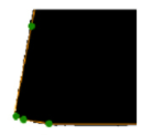
Initial roughing wheel corner radius: 0.05mm | 
Final roughing wheel corner radius: 0.5mm |
The invisible work of the finishing wheel
Finishing wheels for pinch grinding generally have grit sizes from 800 to 1,200, which is an average particle diamond size of 5µm. In our tests, the DOC set for the finishing wheel was approximately 0.05mm radially. The wheel corner breakdown experienced by the roughing wheel caused the actual DOC for the finishing wheel to be much greater than the expected 0.05mm – ‘invisible’ work to the naked eye. Doubling the amount of work of the finishing wheel will generate a significantly higher force per grit in the finishing wheel. This will result in excessive heat generation, causing the finishing wheel to lose its form due to bond deformation, which needs to be avoided. This can be achieved by choosing the right speed ratio between the workpiece and roughing wheel.
Another example of this ‘invisible’ work done by the finishing wheel is in surface generation. Variations on the surface finish generated by the roughing wheel can also affect the surface finish imparted by the finishing wheel. The surface finish left by the roughing wheel isn’t always noted and again, is usually optimised by the finishing wheel. The better the finish that the roughing wheel produces the less work the finishing wheel has to do, which means it will last longer.
A faster grinding surface speed (a higher grinding wheel rpm) will produce smaller chips, generating a finer surface finish on the part. In cylindrical grinding, it is also important to keep an eye on the speed ratio between the roughing wheel and the blanks being ground. This is calculated by finding the ratio between the grinding wheel m/s and workpiece m/s. A rule of thumb for cylindrical grinding of similar parts is to keep the speed ratio around 100:1.
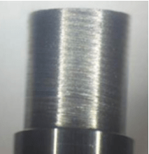
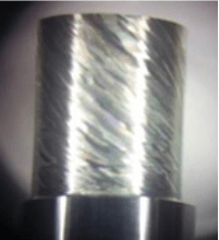
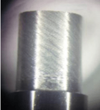
The three images of finishes show how changes in the wheel and workpiece speed can affect surface finish on a tungsten-carbide blank (roughing wheel only). For the part in these images, the finest finish was obtained at a higher roughing wheel speed of 50m/s. The slower roughing wheel RPM generated larger chips — therefore, higher peaks and valleys on the surface of the blank. This results in slightly more aggressive material removals required by the finishing wheel, which can accumulate in an order of a few hundred parts.
| 
| 
|
Wheel speed: 50 m/s Work speed: 0.5 m/s Ratio: 100:1 The finest surface finish is obtained at a speed ratio of 100. | Wheel speed: 40m/s Work speed: 0.5 m/s Ratio: 80:1 Work speed was maintained but wheel speed was reduced, generating a 20% lower speed ratio & imparting a poor surface finish. | Wheel speed: 40 m/s Work speed: 0.35 m/s Ratio: 114:1 Poor surface finish was alleviated by lowering work speed & bringing speed ratio up to 114. |
As can be seen, pinch grinding offers a number of benefits, not least from the invisible work of the finishing wheel. By carrying out the cutting tool blank grinding in one step rather than two, manufacturers can save time and money, while at the same time producing a better surface finish.